How to transfer pictures and video from your iPhone to Windows without it failing 100% of the time

I’m writing this post today because it’s unimaginable that to me in 2019 you can’t just plug a device as common as an iPhone into a device as common as a PC running windows and expect to transfer your pics and vids successfully. It has LITERALLY been years since I’ve tried to do this and had it work on the first try. Usually it takes dozens of tries, and ultimately results in me frustratingly deleting a bunch of pictures and videos until it can complete successfully. I remember using a digital camera in 1996 that was easier to get pictures off than this! Insanity!

Today, is an exception. I REALLY needed a group of videos I’ve taken on my iPhone X transferred to my PC for editing, and now, after THREE HOURS of failed attempts, I have found the holy grail secret trick. Apparently, by default Apple thought it would be smart to try and have their iOS devices do some sort of automatic voodoo where it converts media types on the fly to be more native to the device it’s transferring them to. Problem is, they must have only tested it on a pic of a bagel in the break room, and a 5 second video. It chokes on media created right on your iOS device all the time. Forgot about 3-rd party pics or vids you may have saved to your local camera roll. If you did that, you’re 100% guaranteed to fail. Windows 7, Windows 10, doesn’t matter. iPhone 6, iPhone 7, iPhone 8, iPhone X series. . all fail with a message like “a device attached to the system stopped responding”, or it just gets stuck. Unplug it, plug it back in and it doesn’t even show up. That’s par for the course. Ok, I’m done ranting, here’s the solution:

On your iOS device, goto ‘Settings’ -> ‘Photos’ -> ‘Transfer to MAC or PC’ and select “Keep Originals”.

That’s it. It’s that easy. It even speeds up the transfer, SIGNIFICANTLY.

Enjoy having all your pics and vids on the FIRST try. Do note though that since it’s now NOT converting media on transfer, the file types might be different than what you expect. For example, you get HEIC files instead of JPG’s. Read more info on HEIC files here if that’s a new thing to you.

2018/2019 Dual Sport Maintenance Interval Comparison

Link to the actual spreadsheet:

Dual Sport Bike Maintenance Interval Comparison

CRF450L Ride Review: Coming from a WR250R


New bike time!

24-Channel Raspberry Pi Fireworks Control System

Every year I do a modest fireworks show for our 4th of July Party.  It’s canister mortars, bricks, mines, spinners, etc.  Every year I end up spending the whole time either messing with buttons for the stuff I’ve e-matched, and/or fiddling with fuses. I never get to ’see” the show, and it’s never timed in the way to deliver the most impact.  This year, I decided it was time to automate the show so I could enjoy it as well.   As such, the Mark I ‘KaBoom’ fireworks controller was born.

I decided 24 channels was enough for me (that’s about the total number of fireworks we launch each year), but you could easily modify this basic design to accommodate at least 36 channels with 1 more relay and a 2nd 12-channel wireless unit (more on that later).  Features of the Mark I ‘KaBoom’ include: 12 Wired Control Channels, 12 Wireless Control Channels, Wi-Fi web-page control from your phone or tablet (no internet connection required), Individual Live Manual Channel Control for fire/on/off, Keyed Arming Protection (won’t fire without the key in and turned), 100% Self-Powered, Script-able control (schedule delays and order of firing by writing basic shell scripts, controllable from the Wi-Fi web interface).

Here’s the exact actual parts I used to build the fireworks controller:

(3) 8-Channel Relay Modules

(1) DC-DC Regulated Power Buck

(1) Raspberry Pi3 B+

(1) 1.2Ah 12v SLA Battery

(2) SPST Round Rocker Switches

(1) Key Switch

(1) Micro-USB Cable

(1) Generic 12-ch Wireless Fireworks TX w/RX units

(2) RJ-45 Break-Outs

(1) 80-Piece Breadboard Wire Assortment

(1) Analog Panel Voltmeter

(3) 12-position terminal blocks

You’ll also need some kind of box to put your project in, and some assorted small pieces of wood. I used an old wine box I found with 3-D printed parts and a hot glue gun to hold most things together.

In short, here’s the theory of operation,  There’s 26 usable GPIO’s on the Pi3 B+.  24 of them are wired to the 24 relays.  12 of those relays, when thrown, send 12v to the wired RJ45’s on the back (6 channels per jack).  This directly triggers the e-matches to ignite the fireworks.  The other 12 relays control the 12 wireless firing buttons on the remote that comes with the generic 12-channel fireworks controller.  To do this, those relays short a shared ground pin to the ‘on’ pin of each push button switch (see the pics below to see the wiring).  I used an old parallel printer cable for the necessary wires, but anything would work.  You need 15 wires in total for the fireworks remote.  2 for 12-volt power (supplied only when the arming key is on, 1 for the shared ground, and 12 for the button pins.

To configure the Pi’s Wi-Fi for local access, I followed this great guide at the Raspberry Pi Website:

https://www.raspberrypi.org/documentation/configuration/wireless/access-point.md

I used the Pi’s wired RJ-45 connection for the test/dev work.  All of the control software uses standard python libs for the GPIO pin control to drive the relays, and basic bash scripts running as CGI in Apache.  Boards were all mounted using custom 3-D printed stand-offs, and I made a ton of custom 3-D printed parts for things like the handle feed-thru’s, lid prop, control cover stand-offs with threaded caps, battery hold-down, etc.  This stuff could all be skipped or accomplished with basic tools, some wood scraps,  and more hot glue, but I was going for a certain look and finished quality.  Actual interface to the fireworks e-matches is the terminal blocks at the end of 60′ lengths of solid-copper cat5e.

Want another 12 channels?  It occurred to me after the initial design that you could add another 12-channel RX/TX set, wired to the same 12 relays you used for the first wireless remote and add 1 more relay to control which remote (TX) gets 12v power when the channel is fired as sort of a ’shift register’.

Credit for the stenciled artwork on the box and the graphic in the web/app goes to Banksy.  Hopefully he doesn’t mind me using his imagery :)

Overall, I am really happy with how this project turned out.  It cost less than half what a scriptable 24-channel unit (with the necessary RX/TX modules) would cost, and was a bunch of fun to design and build.  Even had my 9-yr old interested through the process.  She was checking in each time I worked on it to see what was new/working.

I’ll post up a video of the full show when it happens this 4th of July, but here’s 3 test shots, timed a half-second apart from left to right:

https://www.youtube.com/watch?v=xHI18-IAhEE (taken from DJI Mavic drone)

More pics below, and full size images available on my gallery page:

—–< EDIT >—–

Here’s the video of our show from this 4th of July!:

https://youtu.be/OuWJh7eaRwo

Pro Tip – Subaru BRZ, Scion FR-S, Toyota 86 Jumper Cable Storage

Picture says it all!

I bought a set of these and an air pump for all our vehicles years ago.  Originally I just had them on the trunk floor, but this sucks for two reasons:

1) They slide around when I slide the car around.

2) They’re often in the way

A third advantage is you’re lowing your center of gravity, just a teency bit :)   Hard to tell from the pic, but the trunk floor sits 100% flush with these in here, and I never hear them moving/rattling.  They basically fit perfect.

Need a set?  These are the exact ones I purchased:

https://amzn.to/2rQk6kr

Not having a set of cables and needing a jump is a stupid reason to have to call for a tow or help.

Anet A8 – Official Mod Survival Guide – Part 1

The Anet A8 takes a lot of heat on the popular 3-D printing waterholes for some well-known issues, but the reality is that you’re getting quite a bit for your hard-earned dollars, and those well-known issues are easy to fix/mod.

Yes, there’s other options out there, like the Maker Select Mini, or the Wanhao Duplicator i3 V2, but all told, you’ll spend less overall on the A8 + mods, AND have a better working printer than the popular competitors after the mods are completed.

First, some basics.  The A8 is an FDM printer with a build size of 220 x 220 x 240.  This is a pretty generous build size for this price category, and will cover most needs.  The A8 will print PLA or ABS, as well as some other exotics given the cooled extruder and heated bed.   Personally, I stick with PLA since there’s no odor or health risks.  ABS is better for printed items used in applications where heat is a concern, but it’s tougher to print with, and off-gasses lots of harmful nasty stuff during printing.

The A8’s key weaknesses are inadequate high-current connections, a flexy frame, and loose-fitting mechanical components.  I think the latter was actually intentional to make them easy to assembly.  Speaking of assembly, do not be afraid to buy this printer as a kit.  I had zero experience in 3D printing prior to a few months ago, but jumped in head-first with the A8 in kit form.  By building yourself, you learn how all the components work and fit together, making maintenance and tuning much less of a mystery.  Only the most basic tools are required, and they’re included with the printer.

Mod #1 – Cost: $11.97 – Blue painter’s tape for the build platform

I guess this one isn’t really a mod, since the printer does ship from the factory with a form of painter’s tape on the bed, but this is the stuff you want to replace that with when the factory stuff wears out.  I generally get ~5-10 prints on a layer of painter’s tape before I replace it, so a 60-yard roll will go a long way.  The 2.83 wide stuff from 3M only requires 3-rows to cover the whole build plate, and avoids a seam in the center of the bed.  As such, small prints have no seam underneath.  Painter’s tape gives you a nice matte lightly-textured finish on the bottom of printed parts.  Some folks prefer printing on borosilicate glass for the glossy finish, but glass comes with it’s own challenges, and in my opinion, tape is just easier to work with, and I actually like the lightly textured matte finish.

Mod #2 – Cost: $5.83 – Shimming your linear motion rods (more tape)

For ease of installation, the vertical linear motion rods (the smooth vertical rods) on the A8 are loose fitting.  Unfortunately, they’re a bit *too* loose fitting.  If you grab one of the vertical linear motion rods at the bottom, just above one of the z-axis steppers, you can shift it around approx. .5mm in any direction.  That might not sound like a lot, but a layer shift when printing of even 1/5th of that is easily perceptible, and these certainly *do* shift around when printing. especially if the nozzle encounters any resistance when hopping from section to section on a print.  I’ve seen folks drill holes in the frame plates and add grub screws, but honestly, this is overkill, and you risk cracking your frame.  The most simple fix is to just trim some vinyl electrical tape to about 1/4″wide and ~3/4″ long and just wrap it around the very ends of the rods top and bottom.  So this *after* the rods are inserted, and the x-axis idlers are in place.  I’ll pull the bottom rod out just enough to clear the hole, wrap it with one wrap of tape, and then twist it back into the bottom hole.  For the top, I’ll just pop off the whole top plate for that side (only two screws), and the single wrap of tape, and then fit the top plate back over the rod.  You’ll need to do this each time you take  the printer apart in the future, which is why I suggest using the good quality scotch vinyl tape.  It comes off cleanly, and doesn’t turn into a pile of sticky goo.

Mod #3 – Cost: $~35.00 – Install MOSFET’s and better power connectors

The power control circuits in the A8 from the factory are weak, as are many of the connectors.  I’ve already got a write-up on adding MOSFET’s to the A8, but to that, I’d add that you should also replace the connector to the heatbed.   I soldered leads directly to the pins on the heatbed, and placed a deans-style connector an inch or so back.  I also replaced the heatbed wiring with nice soft silicone-jacketed wire to handle the flex when the heatbed moves back and forth.  If you’re not a fan of the dean’s style connectors, XT-60 are another good choice, and a bit easier to solder.   I used JST connectors to maintain a quick-disconnect for the thermistor leads as well.

Stay tuned for Part 2 coming soon!

We didn’t start the fire: Add MOSFET’s to your 3D printer

I’ve gotten bitten by the 3D printer bug recently, and picked up an Anet A8  around Christmas.

It’s your typical corner-cutting Chinese kit printer, but it’s one of the nicer ones as far as features and electronics components.  Unfortunately, like many cheap 3D  printers, the wire and electronics for delivering power to the bed and hot end is inadequate.  Let’s take a step back for a moment, and understand the basic electronics.

The key components are the power supply, the steppers, the LCD, control board, heated bed, and hot end.  Most of these use very little power.  Even the steppers all working at once use less than a few amps.  The bed and hot end though are power hungry.  I found the bed on my Anet A8 draws ~11 amps, and the hot end ~3 amps (@12v) .  This a lot of current to push through the otherwise low power mainboard, especially for the bed.  This will ultimately lead to failure, and you’ll be hunting for  a whole new mainboard, or worse, putting out a fire.

The solution: get that high current off the mainboard!  Adding larger and separate mosfets to handle power deliver to the bed and nozzle takes all that strain off the mainboard, and will extend it’s life dramatically (and reduce the chance of overheating which could lead to fire).  You could probably get away with just adding a mosfet for the bed, but I would suggest adding one for the hot end too.  You’re re-wiring anyway, and they’re cheap, so may as well get as much current off the mainboard as possible.  I used two of these mosfets.

The second problem is the wiring itself.  The wire supplied in most kits suffers two key problems:

1) It’s bare copper, which over time loosens under the screw terminals, leading to resistance, which in turns causes the terminal to overheat and burn.

2) It’s often undersized (I’ve seen kits with 18ga wire that’s carrying close to 20 amps).

The wiring is an easy fix.   When adding the mosfets (wiring diagram further down), use 14ga wire for the run to the bed mosfet, and a minimum of 16ga for all other DC power runs.   Here is the link to the good silicone 16ga wire I used, and here is the link to the good 14ga wire.  MAKE SURE YOU TIN ALL THE ENDS, OR USE QUALITY CRIMPED ENDS.  I’m personally a fan of tinning all the ends. I’ve never had an issue with a properly tinned wire under a screw terminal.  Come back and snug up the screws in a few days of use.  They will stay tight, have VERY low resistance, and the solder ensures an even connection across all the wire strands.  If you don’t have a good soldering iron, this is a good time to get one.  I use the Hakko FX888D, and it’s exceptional.  You’ll never buy another iron.  If the Hakko is out of your price range, this one would be my choice for a basic iron.

Here’s the wiring diagram that brings it all together (click to view larger):

If you happen to also have Anet A8, I designed a mount to hold both of these mosfets, just above your mainboard:

Thanks for reading!

Shell Script To Control Belkin WeMo’s

It’s no surprise I’m a huge fan of home automation and tech toys, and I recently picked up a pair of Belkin WeMo’s.

You **have** to set them up with the app they supply for smartphones, but after that I hoped I could find a way to control them directly. Belkin has collected quite a few negative reviews for these devices, and it’s a shame, because the hardware seems real solid.  It’s their current apps that leave a LOT to be desired.  Clearly the issues they’re having getting the app side right are driving down the reviews.  Fortunately, I could care less how the app experience is, since I only needed it to initially deploy the devices, and planned from the get-go to write my own code to control them.

Numerous folks have written tools to control some of the functions of these, but everything I came across was dependent on other libraries, was incomplete, or didn’t work when I tested it.  I like plain-old vanilla shell scripts that I can just run from any local machine, and I’ve hacked up various XML snippets I’ve found and just rely on curl for the following script that I put together:

#!/bin/sh
#
# WeMo Control Script
#
# Usage: ./wemo_control IP_ADDRESS ON/OFF/GETSTATE/GETSIGNALSTRENGTH/GETFRIENDLYNAME
#
#

IP=$1
COMMAND=$2

PORTTEST=$(curl -s $IP:49152 | grep “404″)

if [ "$PORTTEST" = "" ]
then
PORT=49153
else
PORT=49152
fi

if [ "$1" = "" ]
then
echo “Usage: ./wemo_control IP_ADDRESS ON/OFF/GETSTATE/GETSIGNALSTRENGTH/GETFRIENDLYNAME”
else

if [ "$2" = "GETSTATE" ]

then

curl -0 -A ” -X POST -H ‘Accept: ‘ -H ‘Content-type: text/xml; charset=”utf-8″‘ -H “SOAPACTION: \”urn:Belkin:service:basicevent:1#GetBinaryState\”" –data ‘<?xml version=”1.0″ encoding=”utf-8″?><s:Envelope xmlns:s=”http://schemas.xmlsoap.org/soap/envelope/” s:encodingStyle=”http://schemas.xmlsoap.org/soap/encoding/”><s:Body><u:GetBinaryState xmlns:u=”urn:Belkin:service:basicevent:1″><BinaryState>1</BinaryState></u:GetBinaryState></s:Body></s:Envelope>’ -s http://$IP:$PORT/upnp/control/basicevent1 |
grep “<BinaryState”  | cut -d”>” -f2 | cut -d “<” -f1 | sed ’s/0/OFF/g’ | sed ’s/1/ON/g’

elif [ "$2" = "ON" ]

then

curl -0 -A ” -X POST -H ‘Accept: ‘ -H ‘Content-type: text/xml; charset=”utf-8″‘ -H “SOAPACTION: \”urn:Belkin:service:basicevent:1#SetBinaryState\”" –data ‘<?xml version=”1.0″ encoding=”utf-8″?><s:Envelope xmlns:s=”http://schemas.xmlsoap.org/soap/envelope/” s:encodingStyle=”http://schemas.xmlsoap.org/soap/encoding/”><s:Body><u:SetBinaryState xmlns:u=”urn:Belkin:service:basicevent:1″><BinaryState>1</BinaryState></u:SetBinaryState></s:Body></s:Envelope>’ -s http://$IP:$PORT/upnp/control/basicevent1 |
grep “<BinaryState”  | cut -d”>” -f2 | cut -d “<” -f1

elif [ "$2" = "OFF" ]

then

curl -0 -A ” -X POST -H ‘Accept: ‘ -H ‘Content-type: text/xml; charset=”utf-8″‘ -H “SOAPACTION: \”urn:Belkin:service:basicevent:1#SetBinaryState\”" –data ‘<?xml version=”1.0″ encoding=”utf-8″?><s:Envelope xmlns:s=”http://schemas.xmlsoap.org/soap/envelope/” s:encodingStyle=”http://schemas.xmlsoap.org/soap/encoding/”><s:Body><u:SetBinaryState xmlns:u=”urn:Belkin:service:basicevent:1″><BinaryState>0</BinaryState></u:SetBinaryState></s:Body></s:Envelope>’ -s http://$IP:$PORT/upnp/control/basicevent1 |
grep “<BinaryState”  | cut -d”>” -f2 | cut -d “<” -f1

elif [ "$2" = "GETSIGNALSTRENGTH" ]

then

curl -0 -A ” -X POST -H ‘Accept: ‘ -H ‘Content-type: text/xml; charset=”utf-8″‘ -H “SOAPACTION: \”urn:Belkin:service:basicevent:1#GetSignalStrength\”" –data ‘<?xml version=”1.0″ encoding=”utf-8″?><s:Envelope xmlns:s=”http://schemas.xmlsoap.org/soap/envelope/” s:encodingStyle=”http://schemas.xmlsoap.org/soap/encoding/”><s:Body><u:GetSignalStrength xmlns:u=”urn:Belkin:service:basicevent:1″><GetSignalStrength>0</GetSignalStrength></u:GetSignalStrength></s:Body></s:Envelope>’ -s http://$IP:$PORT/upnp/control/basicevent1 |
grep “<SignalStrength”  | cut -d”>” -f2 | cut -d “<” -f1

elif [ "$2" = "GETFRIENDLYNAME" ]

then

curl -0 -A ” -X POST -H ‘Accept: ‘ -H ‘Content-type: text/xml; charset=”utf-8″‘ -H “SOAPACTION: \”urn:Belkin:service:basicevent:1#ChangeFriendlyName\”" –data ‘<?xml version=”1.0″ encoding=”utf-8″?><s:Envelope xmlns:s=”http://schemas.xmlsoap.org/soap/envelope/” s:encodingStyle=”http://schemas.xmlsoap.org/soap/encoding/”><s:Body><u:ChangeFriendlyName xmlns:u=”urn:Belkin:service:basicevent:1″><FriendlyName>Pool Filter</FriendlyName></u:ChangeFriendlyName></s:Body></s:Envelope>’ -s http://$IP:$PORT/upnp/control/basicevent1 |
grep “<FriendlyName”  | cut -d”>” -f2 | cut -d “<” -f1

else

echo “COMMAND NOT RECOGNIZED”
echo “”
echo “Usage: ./wemo_control IP_ADDRESS ON/OFF/GETSTATE/GETSIGNALSTRENGTH/GETFRIENDLYNAME”
echo “”

fi

fi

Copy/Paste or download here: wemo_control.sh

Usage is:   ./wemo_control IP_ADDRESS ON/OFF/GETSTATE/GETSIGNALSTRENGTH/GETFRIENDLYNAME and the functions are pretty self-explanatory.

The usual disclaimer applies.  I don’t write code for a living and there’s probably gross inefficiencies and poor syntax, but it WORKS.

Enjoy :P

AcuRite Acu-Link Internet Bridge (09150TRX): Accessing Local Data

AcuRite has been threatening the release of this product for well over a year, and it’s finally out.  Being a bit obsessive about data in and around my home, (check-out my IP Thermostat install and custom interface) I *HAD* to have one of these.

The “idea” is that you buy the Internet Bridge from AcuRite, and either with your existing sensors from their other products (many are compatible), or with the purchase of additional sensors, live data is transmitted to their “MyBackyardWeather” web site and you can view the data while you’re away and track trends etc.  They even offer a “forecasting” widget.

To get started, I ordered the internet bridge, a tower sensor, and a floating pool sensor.   The bridge is 80 bucks, and the sensors are very reasonably priced at ~ $8 for the tower sensor and $20 for the floating sensor.  They’re shipping is a bit slow, but everything arrived well packed and the build quality of all the devices is quite good.  The tower sensor supplies both temperature and humidity data, and honestly 8 bucks for one of these is a great price.   You’d be hard-pressed to buy just the sensors for an arduino or pi build for that money.

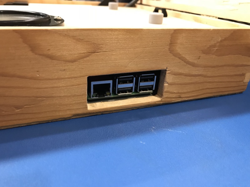
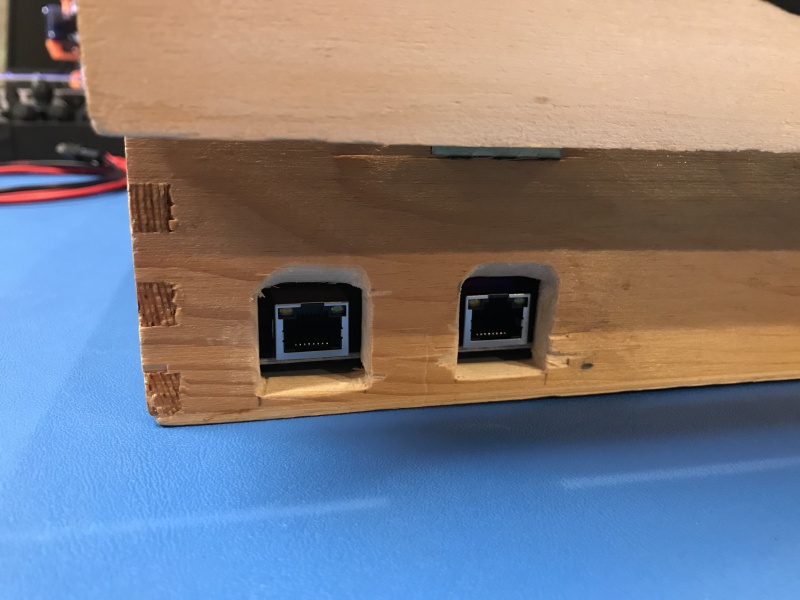
The bridge has a flip-up antenna and two connections, one RJ-45 for a network cable, and one jack for the power plug.  Since the protocol and any real info about how the bridge “talks” to their web site is unpublished and unknown, I figured I’d give it the full packet capture and analysis treatment.   To do this, I added a static DHCP IP mapping for the MAC address of the Internet Bridge to my router/firewall so as soon as it came online, I’d know the IP address.  The MAC address of the Internet Bridge can be found right on the bottom of the unit.  This MAC address is also the “ID” that AcuRite uses to associate your data sources with your account on MyBackyardWeather, but I’ll get to that later.  After setting up the static IP mapping, I enabled packet capture for any TCP/UDP connections from that IP out to the net.  Time to plug it in!

Once connected, the Internet Bridge did two things:

1) started sending sensor data to the Acu-Link web app

2) started downloading new firmware line-by-line with a POST for each new line as one completed

I pulled the connection before the firmware update could complete (just in case), and started to take a closer look at the data sent to the Acu-Link web app via the packet capture.  To my surprise, it looked like the sensor data was being sent  cleartext in a simple HTTP POST, one POST for each sensor in range of your Internet Bridge.  Next, I tried reconnecting the bridge, but this time with WAN access blocked, and ran a full port scan.  Only port 80 was open, and a visit to the Bridge’s local IP in a browser yielded a simple status page informing me that a firmware update was in process.   In the hope that more useful data would be presented when not in the “firmware-update” state, I permitted WAN access and let the firmware update complete.

Once the firmware update completed, the simple status page showed the sensors in range, their signal, and the option to send a POST to the bridge to toggle the LED’s on and off, but no actual sensor data was shown, and there’s nothing to click on, save for the LED toggle.  I tried forcing an error that might yield useful information with various POST’s and GET’s to the simple web interface on the Internet Bridge, but never got more than a 404 or the same status page.

Since querying the data directly from the Internet Bridge seemed unlikely without new information, I returned to looking at the data the Internet Bridge POST’s to Acu-Link, which was a little different now after the update.  The actual variables had additional digits and letters, but the values were still cleartext within this group of digits.  Here’s what the HTTP POST looks like when my Internet Bridge sends data for my tower sensor:

id=############&sensor=11423&mt=tower&humidity=A0590&temperature=A018000000&battery=normal&rssi=4

. . . . . let’s break it down and look at each piece:

id=############

I obfuscated the actual value here, but this is the MAC address of your Internet Bridge

sensor=11423

This is the sensor identifier, and appears to be unique for each sensor, though I only have one tower sensor, so I can’t be sure

mt=tower

This is the type of sensor, probably stands for “model type” if I had to guess

humidity=A0590

The 3rd-5th digits are the relevant ones here, with a decimal point required between the 4th and 5th digits, yielding a value of 59.0 for humidity

temperature=A018000000

Again, the 3rd-5th digits are the important ones here, but the 2nd digit serves the role of  denoting a positive or negative reading as well.  If the reading is positive, it’s a “0″, if it’s negative, it’s a “-”.  This value is also in Celsius, so if you want Fahrenheit, you’ll need to convert it.

battery=normal

This one seems fairly obvious, but I didn’t try inserting an older set of batteries to see what it reports when not “normal”

rssi=4

This denotes the received signal level for the specific sensor, and varies from 0-4

All of this data is super-easy to parse in just about any language.  I’m no programmer, but I’m “dangerous” with BASH scripting, so I figured I could probably whip something up, but how do we get the data if you can’t request it?  TCP dumps are nice for post-analysis. but a pain to do anything with real-time.  An HTTP proxy server with some customization would be an option to intercept the data, as well as IDS with some custom rules that took actions like parsing the data and writing out values that could be sucked up from something else, but I had something even “dirtier” in mind.

Let’s dig into what happens for data to get from the Internet Bridge to Acu-Link’s site from power-on to data.

1) The Internet Bridge powers up and gets an IP, gateway and DNS servers via DHCP (your router typically hands out this info)

2) The Internet Bridge resolves “http://www.acu-link.com” using DNS

3) The Internet Bridge starts making regular HTTP POST’s to the Acu-Link web service at: “http://www.acu-link.com/messages”

4) The Acu-Link web service responds back to each POST from the Internet Bridge with a SUCCESS, and the current firmware version.  (presumably if the FW version is higher than installed on the Internet Bridge, this is what initiates the downloading and install of new firmware).

Knowing the above, I figured the easiest way to get sensor data locally would be to “trick” the Internet Bridge into sending it to me instead of Acu-Link.  To do this, I configured my router/firewall (I use pfSense) to “override” www.acu-link.com by having the local DNS service resolve the hostname to a local IP on my network instead of the “real” IP on Acu-Link’s network.   If you can’t override hostnames or zones on your router/firewall with the local DNS service, or your router/firewall doesn’t offer a local DNS services, there’s several freeware DHCP/DNS software pkgs that you could run on a PC on your network to accomplish that same thing.

Now that I have my Internet Bridge sending it’s data to an IP on my network, I needed something to receive it.  I wrote a simple BASH script to replace the functionality of the “messages” web service at Acu-Link:

#!/bin/sh
echo “Content-type: text/html”
echo

echo “SUCCESS”

POSTDATA=$(cat | tr -d ‘ ‘)

FIELD=1
while [ $FIELD -le 15 ]
do

DATA=$(echo $POSTDATA | cut -d”&” -f$FIELD)
VARIABLE=$(echo $DATA | cut -d”=” -f1)
VALUE=$(echo $DATA | cut -d”=” -f2)

if [ $VARIABLE = id ]
then
ID=$VALUE

elif [ $VARIABLE = sensor ]
then
SENSOR=$VALUE
echo “$VARIABLE=$VALUE” > ../weather_data/”$ID”_$SENSOR.txt

elif [ $VARIABLE = temperature ]
then
WHOLE=$(echo $VALUE | cut -c 2-4)
DECIMAL=$(echo $VALUE | cut -c 5)
CELSIUS=$(echo $WHOLE.$DECIMAL)
VALUE=$(echo “$CELSIUS * 1.8 + 32″ | bc -l)
echo “$VARIABLE=$VALUE” >> ../weather_data/”$ID”_$SENSOR.txt

elif [ $VARIABLE = humidity ]
then
WHOLE=$(echo $VALUE | cut -c 3-4)
DECIMAL=$(echo $VALUE | cut -c 5)
VALUE=$(echo $WHOLE.$DECIMAL)
echo “$VARIABLE=$VALUE” >> ../weather_data/”$ID”_$SENSOR.txt

elif [ $VARIABLE = battery ]
then
echo “$VARIABLE=$VALUE” >> ../weather_data/”$ID”_$SENSOR.txt

elif [ $VARIABLE = rssi ]
then
echo “$VARIABLE=$VALUE” >> ../weather_data/”$ID”_$SENSOR.txt

else
sleep 0
fi

(( FIELD++ ))

done

This reads the raw POST data, then steps through “if” handlers I kludged together to look for each data type.  Grabbing additional data from other sensors would be done just be adding additional handlers for each data type (wind speed, rainfall, etc.).  The script then dumps the data out to files named based on the MAC address and sensor ID’s to a writable directory. I can then query this data from other scripts, or POST it elsewhere (like weather underground, etc.).  Personally, I have a whole web app I’ve written for my IP thermostat that I WAS using external data for the display of outdoor temp/humidity.  Now I’m using ACTUAL data from my AcuLink sensors.   The above script returns just a simple SUCCESS to the Internet Bridge, but the bridge doesn’t seem to care, it just keeps on truckin’ sending more data.  A side-effect to this setup is that your bridge won’t update it’s firmware (possibly breaking any reliance you have on the current behavior) unless you remove your custom DNS entries and let it talk to the “real” Acu-Link web service.

Now, you could stop there and call it a day, but the obvious con to this setup is that Acu-Link’s MyBackyardWeather no longer gets your weather data, and the out-of-the-box graphing, weather forecast’s, mobile apps, etc. are pretty cool.   With a SIMPLE addition to my script, I added the original functionality back in by using curl to POST the data to the “real” web service (in addition to stepping through it locally).  Here’s the addiiton:

curl -d “$POSTDATA” http://acu-link.com/messages/ > /dev/null

Notice I used “acu-link.com” instead of “www.acu-link.com”.  This means our override of the www hostname won’t affect our scripts ability to reach the “real” web service.  A quick visit to MyBackyardWeather confirmed it was again getting fresh data.

In summary, AcuRite makes some great weather hardware, and their Internet Bridge and associated sensor’s are no exception.  I wish they would have built this system a bit more “open” and permitted a simple GET request to the bridge for sensor data, but this product is also very new, and they are very encouraging to their users to suggest new features, etc.  There is even mention that they may offer the ability to query this data directly in the future, but in the meantime: hack-on :P

Sennheiser takes a stab at simple, quality.

Check these out!  Sennheiser is showing off their new Momentum headphones at IFA, and wow, they are sweet!

I’m a sucker for simple, industrial, well-crafted design with a touch of style and class and these look like all that and more.  Brushed stainless, real leather, adjustable. .

I do love my Dre beats, but I’m generally tired of  plastic creaky crap “cans” that look like you’re wearing disposable ear protection.

The real proof lies in how they sound, but I’m keeping my finger’s crossed Sennheiser wouldn’t go to this much trouble to have them sound like crap.