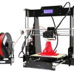
 The Anet A8 takes a lot of heat on the popular 3-D printing waterholes for some well-known issues, but the reality is that you’re getting quite a bit for your hard-earned dollars, and those well-known issues are easy to fix/mod.
Yes, there’s other options out there, like the Maker Select Mini, or the Wanhao Duplicator i3 V2, but all told, you’ll spend less overall on the A8 + mods, AND have a better working printer than the popular competitors after the mods are completed.
First, some basics. The A8 is an FDM printer with a build size of 220 x 220 x 240. This is a pretty generous build size for this price category, and will cover most needs. The A8 will print PLA or ABS, as well as some other exotics given the cooled extruder and heated bed. Personally, I stick with PLA since there’s no odor or health risks. ABS is better for printed items used in applications where heat is a concern, but it’s tougher to print with, and off-gasses lots of harmful nasty stuff during printing.
The A8’s key weaknesses are inadequate high-current connections, a flexy frame, and loose-fitting mechanical components. I think the latter was actually intentional to make them easy to assembly. Speaking of assembly, do not be afraid to buy this printer as a kit. I had zero experience in 3D printing prior to a few months ago, but jumped in head-first with the A8 in kit form. By building yourself, you learn how all the components work and fit together, making maintenance and tuning much less of a mystery. Only the most basic tools are required, and they’re included with the printer.
 Mod #1 – Cost: $11.97 – Blue painter’s tape for the build platform
I guess this one isn’t really a mod, since the printer does ship from the factory with a form of painter’s tape on the bed, but this is the stuff you want to replace that with when the factory stuff wears out. I generally get ~5-10 prints on a layer of painter’s tape before I replace it, so a 60-yard roll will go a long way. The 2.83 wide stuff from 3M only requires 3-rows to cover the whole build plate, and avoids a seam in the center of the bed. As such, small prints have no seam underneath. Painter’s tape gives you a nice matte lightly-textured finish on the bottom of printed parts. Some folks prefer printing on borosilicate glass for the glossy finish, but glass comes with it’s own challenges, and in my opinion, tape is just easier to work with, and I actually like the lightly textured matte finish.
Mod #2 – Cost: $5.83 – Shimming your linear motion rods (more tape)
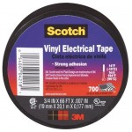
For ease of installation, the vertical linear motion rods (the smooth vertical rods) on the A8 are loose fitting. Unfortunately, they’re a bit *too* loose fitting. If you grab one of the vertical linear motion rods at the bottom, just above one of the z-axis steppers, you can shift it around approx. .5mm in any direction. That might not sound like a lot, but a layer shift when printing of even 1/5th of that is easily perceptible, and these certainly *do* shift around when printing. especially if the nozzle encounters  any resistance when hopping from section to section on a print. I’ve seen folks drill holes in the frame plates and add grub screws, but honestly, this is overkill, and you risk cracking your frame. The most simple fix is to just trim some vinyl electrical tape to about 1/4″wide and ~3/4″ long and just wrap it around the very ends of the rods top and bottom. So this *after* the rods are inserted, and the x-axis idlers are in place. I’ll pull the bottom rod out just enough to clear the hole, wrap it with one wrap of tape, and then twist it back into the bottom hole. For the top, I’ll just pop off the whole top plate for that side (only two screws), and the single wrap of tape, and then fit the top plate back over the rod. You’ll need to do this each time you take the printer apart in the future, which is why I suggest using the good quality scotch vinyl tape. It comes off cleanly, and doesn’t turn into a pile of sticky goo.
Mod #3 – Cost: $~35.00 – Install MOSFET’s and better power connectors
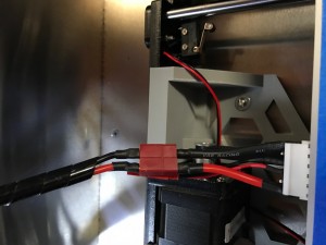
The power control circuits in the A8 from the factory are weak, as are many of the connectors. I’ve already got a write-up on adding MOSFET’s to the A8, but to that, I’d add that you should also replace the connector to the heatbed. I soldered leads directly to the pins on the heatbed, and placed a deans-style connector an inch or so back. I also replaced the heatbed wiring with nice soft silicone-jacketed wire to handle the flex when the heatbed moves back and forth. If you’re not a fan of the dean’s style connectors, XT-60 are another good choice, and a bit easier to solder. I used JST connectors to maintain a quick-disconnect for the thermistor leads as well.
Stay tuned for Part 2 coming soon!