 I’ve gotten bitten by the 3D printer bug recently, and picked up an Anet A8 around Christmas.
It’s your typical corner-cutting Chinese kit printer, but it’s one of the nicer ones as far as features and electronics components. Unfortunately, like many cheap 3D printers, the wire and electronics for delivering power to the bed and hot end is inadequate. Let’s take a step back for a moment, and understand the basic electronics.
The key components are the power supply, the steppers, the LCD, control board, heated bed, and hot end. Most of these use very little power. Even the steppers all working at once use less than a few amps. The bed and hot end though are power hungry. I found the bed on my Anet A8 draws ~11 amps, and the hot end ~3 amps (@12v) . This a lot of current to push through the otherwise low power mainboard, especially for the bed. This will ultimately lead to failure, and you’ll be hunting for a whole new mainboard, or worse, putting out a fire.
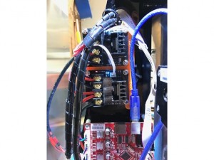
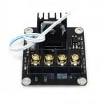
The solution: get that high current off the mainboard! Adding larger and separate mosfets to handle power deliver to the bed and nozzle takes all that strain off the mainboard, and will extend it’s life dramatically (and reduce the chance of overheating which could lead to fire). You could probably get away with just adding a mosfet for the bed, but I would suggest adding one for the hot end too. You’re re-wiring anyway, and they’re cheap, so may as well get as much current off the mainboard as possible. I used two of these mosfets.
The second problem is the wiring itself. The wire supplied in most kits suffers two key problems:
1) It’s bare copper, which over time loosens under the screw terminals, leading to resistance, which in turns causes the terminal to overheat and burn.
2) It’s often undersized (I’ve seen kits with 18ga wire that’s carrying close to 20 amps).
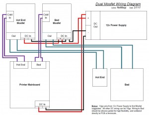
The wiring is an easy fix. When adding the mosfets (wiring diagram further down), use 14ga wire for the run to the bed mosfet, and a minimum of 16ga for all other DC power runs. Here is the link to the good silicone 16ga wire I used, and here is the link to the good 14ga wire. MAKE SURE YOU TIN ALL THE ENDS, OR USE QUALITY CRIMPED ENDS. I’m personally a fan of tinning all the ends. I’ve never had an issue with a properly tinned wire under a screw terminal. Come back and snug up the screws in a few days of use. They will stay tight, have VERY low resistance, and the solder ensures an even connection across all the wire strands. If you don’t have a good soldering iron, this is a good time to get one. I use the Hakko FX888D, and it’s exceptional. You’ll never buy another iron. If the Hakko is out of your price range, this one would be my choice for a basic iron.
Here’s the wiring diagram that brings it all together (click to view larger):
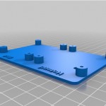
If you happen to also have Anet A8, I designed a mount to hold both of these mosfets, just above your mainboard:
Thanks for reading!


Brian C
February 7th, 2017
Very cool writeup…if you have a heated bed…its ALWAYS best to offload the high current flow away from the board…better to smoke a $7-10 module than a $40-50 controllerboard
Andy
February 17th, 2017
Personally, I use fork crimp connectors when mounting to these types of screw terminals, like these:-
https://ae01.alicdn.com/kf/HTB1GASNLpXXXXcKXXXXq6xXFXXXB/Best-Promotion-25PCS-4-font-b-Sizes-b-font-Blue-Insulated-Fork-Wire-font-b-Connector.jpg
Good connection, easy to remove, no stray wires.
John Guenther
February 24th, 2017
I just replaced the main board on my Anet A8, not planning on doing that again. I found your mount for dual mosfet’s on Thingiverse, ordered a couple from Amazon.com so I could get them quickly and now they are installed. I will be ordering two more for the HyperCube I am building, don’t want to blow the new RAMPS 1.4 board I will be using with it. Thanks.
DanielS
March 11th, 2017
What a perfect writeup and mount! Thanks for sharing all of this info, I just purchased an Anet A2 and can’t wait for it to show up!
Been doing alot of research and the dual mosfet and dual power supply seem to be one of the most highly recommended upgrades to do early in the printers life cycle and I can’t find or design a better mosfet mount then the one you provided!
(Might have to remix it to work with the A2 and will give full credit if I do of course!)
So yea, thanks again for a simple diagram and perfect mount!
me
March 30th, 2017
Nice writeup. I noticed you wired the the mosfets in a serial way. (I’m not an electrician, but i think that is what you call it). Could you also wire them each individually connected to the power supply?
Rich
March 30th, 2017
Hi,
They are not wired in a series on my diagram. They are wired in Parallel. Please see the below page for more info about the two types of circuits. Your MOSFET’s should be wired in parallel.
https://www.allaboutcircuits.com/textbook/direct-current/chpt-5/what-are-series-and-parallel-circuits/
-Rich H.
Kyle
April 6th, 2017
Nice write up, and I have done this with my printer (also swapped out the bed as I had an issue with the original bed being wrapped, the new one is a 200W at 12 volts pad + plate vs the PCB style), but I ran into an issue. I have the Control In hooked up, I have cable from the power supply going to the In on the MOSFET and the bed hooked up on the other in. As soon as I plug the printer in, the bed starts heating up and the MOSFET gets crazy hot, even the board gets hot. I haven’t even told the bed to turn on at this point and it is already trying to heat it up. I only get the D2 red light on the board. Do I have a bad board or am I missing something? I have changed the firmware for Skynet, so I am not sure if that might be the issue or not.
Rich
April 7th, 2017
Hi Kyle,
It sounds like you might have the MOSFET connected wrong. It should barely get warm while running the bed.
Have another look at my wiring diagram, and trace each wire to confirm it’s hooked up right.
-Rich H.
John
April 14th, 2017
Hi Rich, I stumbled upon your article after doing a little research on my new 3D printer (Anet A8). I am keen to drop in some MOSFET modules and off-load the heavy current from the main controller. I am having difficulty finding any units on Amazon that will ship to Australia. I am also having a hard time finding suitable units (>10Amp) on ebay, etc.
I have seen hundreds of MOSFET DC motor driver boards. These are a ‘H-Bridge’ setup, but I am wondering if I can use one of those boards to drive the 2 devices (Bed & Head) ?
eg: https://tinyurl.com/mkzr8zu
Thx for the great article!
Rich
April 17th, 2017
That board is designed for PWM. That’s not to say it wouldn’t hold up under constant duty, but I’d keep searching for one of the std. mosfet boards.
Rog
April 22nd, 2017
Question. The thermister wires. Do they still go to the motherboard or just the contol wires from the mosfets?
Rich
April 24th, 2017
They are unchanged, they still goto the mobo.
Kev
April 26th, 2017
Hey thanks for the write up! Quick question, I am new to wiring electronics and was wondering about how to do the two wires in a single terminal. I was planning on using a spade crimp but I do not think I can fit both wilres to fit in one. Did you just twist the wires together, solder the end and put it in the terminal?
Rich
April 26th, 2017
I tin them, and put one to the right side of the screw, and one to the left. As long as the wire gauges match, or are very close, it’s usually good. There’s debate on whether wires should be tinned before going under a mechanical fastener, since the solder will cold flow a bit, but I’ve found if I tighten them, then re-tighten after a few days of use they stay tight and make good conduct.
Minh Hoang
May 1st, 2017
Hi. Thanks for the article. I just want to ask, why is the mosfet board using 6 connections (2 for power, 2 for output and 2 for input). Why don’t they use the same ground pin? Also do you have any info on how they connect the mosfet to those pins?
I am planning to go buy the mosfet and do it myself.
Rich
May 1st, 2017
Not certain, but my guess is to isolate heating power from board power if you use two power supplies
Chuck
May 13th, 2017
Hey man,
Thanks a ton for the write-up, the links to the parts, and the time and effort to help us newbs. It’s folks like you that keep my faith in the internet alive.
I do have one quick question: I ordered the mosfets that you linked to and they came with crazy short input wires. I had to flip my mobo upside down to make them reach. My concern is that the wires are also crazy skinny. Are you sure it’s kosher to plug those into the bed and extruder’s original power connectors? I’m undergoing this repair job because I’ve already melted a sub-par connection, I’d hate to create one more.
Rich
May 13th, 2017
Yeh, they all come with really short leads or worse, no leads at all. I extended mine to install the mosfets where I did with some wire I had left over from a garage door opener installation (the 2-conductor solid stuff around 22 or 24 AWG). The thin wires are fine, as they only drive the control side of the circuit now, switching the mosfets on and off.
nicolas
May 16th, 2017
Hi there,
Thank you for this post, I just got an A8 (as it looks like fun learning about 3D printing) and everyone is telling me to get a mosfet …. but since I have kids, I’m getting two just for the extra safety (both hotbbed and extruder).
My electronics and electricity knowledge is limited to what I remember from high school (it was a particularly good school but it’s been a hell of a while and I need some confirmation on a couple of things.)
So while I’m waiting for the mosfets to come here, I’ve got a couple of questions.
1) The mosfets come wiith a cable for the control in, but it looks like a 18awg at best;
From what I understand, the amperage going through that part of the circuit is minimal and those wires should be ok…. is this correct ?
2) Looking at the schematics, it looks like both mosfets are in parallel; but in your thingiverse setup pictures it looks both mosfets are connected directly to the PSU.
http://www.thingiverse.com/make:319624
The difference seen in the schematics is made to save some wiring, but both setups are equivalent to my (old) understanding, right ?
In the schematics shown in the blog here, the connectors (the pair coming from the PSU and the pair going to the second mosfet) will be using the same mosfet “DC in” … is there enough space for this or is it too cramped and may risk of causing a short ?
(If anyone has done it -both wires from the same “DC in”- could you put up or send a link to a pic about it ?)
Thanks Guys !
Rich
May 18th, 2017
Mine is wired to match the schematic. I use a single run from the PS and essentially just use the first DC-in on the MOSFET to split the power at that point. As long as you use 14 gauge wire, this is fine.
The ctrl wires carry very little current, and anything 22 gauge or better is sufficient.
-Rich H.
Chucketn
July 2nd, 2017
Does your Mosfet holder require holes drilled in the Anet A8 frame or use existing holes?
Thanks for posing about this.
Rich
July 3rd, 2017
no, uses the existing holes
Douglas
July 6th, 2017
So the control wire to the mosfet hooks to the bed power coming out of the motherboard.
Dale
August 30th, 2017
Hey, in your article, you talk about replacing the wires between the main-board and the heater-block (extruder).. How do I go about doing that? The stock Anet 8A comes with these wires wrapped, tapped, and leading to inside the heater-block..
I mean, I could cut and connect the better-gauged-wires to the lines leading into the heater-block right before the tape-&-wrapping, but then we still have some lower quality wires in the assembly…
Rich
August 31st, 2017
I’m referring to the wires to the heated bed. i have not had any issues with the stock wire for the hot end.
Blake
October 12th, 2017
Thanks for this wonderful article Rich, my Anet A8 is sitting in LA Customs checkin, waiting to ship to Washington State I’ve got my double mossfetts and all the extra goodies waiting here at the house, thanks for the wiring diagram I’m going to do this before I even start trying to print anything this is going to be so much fun ,
I built a CNC plasma table about 10 years ago had to teach myself that whole system and CAD for doing metal, now I want to do 3D printing ,
excellent article really appreciate it thanks again.. hope to start 3D printing in a week or two
Rich
October 12th, 2017
You are welcome, and good luck with the build!
Larry Beck
November 25th, 2017
Great article! I had my original power supply blow up when I inadvertently cycled the power strip it was plugged into. One of the chips near the top of the PS sparked and then caught fire! I replaced the PS with this one: https://www.amazon.com/gp/product/B00LV8TZAG/ref=oh_aui_detailpage_o02_s00?ie=UTF8&psc=1
This PS cost $30 earlier this year and $20 when I bought one yesterday (Black Friday). I had to bring all the 12V lines together to run to the motherboard and cut and tie off the lines I didn’t need. What’s cool about using a PC PS is that there is a 5V line that is always alive that I use to power the Rpi that’s running my Repetier server and there is a line I ran to a switch to turn the PS on. I use Delphi Weatherpack connectors (http://www.jegs.com/i/JEGS/555/10750/10002/-1?CAWELAID=1710730288&CAGPSPN=pla&CAAGID=39714413703&CATCI=pla-293995373017&CATARGETID=230006180039220954&cadevice=m&gclid=CjwKCAiAxuTQBRBmEiwAAkFF1sDlA88RSzfdv2Afl0kO2UwOo8YKKf8cZK6Xk9gBsdVpbCYpma9EHRoCH9EQAvD_BwE) . I like the fact that these connectors are rated to handle 20A (although I like keeping it closer to 10A) and are waterproof. It’s a little spendy to start since you have to buy a $30 crimper but these things have been bullet-proof and are a snap to install after I found instructions on only stripping 1/4″ and crimping the right parts.
Rich
November 27th, 2017
Hi Larry,
I’m glad to hear you had success with your replacement, but I would strongly recommend against using a computer (AT/ATX) power supply. They are designed to have current drawn on their different outputs simultaneously and tend to suffer significant voltage drops if only one output is drawn at a high current. You can get around this by adding some large power resistors to the unused (or lesser-used outputs), but it generates a bunch of heat and generally isn’t worth the effort. That Pi is probably only drawing half an amp on the 5v output, which means the 12v output on the power supply is likely sagging down under 12v when the bed and hotend are pulling current. Measure the 12v output while the printer is warming up.
I would strongly recommend using a proper single-rail 12v power supply from a reputable vendor. Here’s a good example of a well-made 12v PS rated to handle the required current with some headroom:
Mean Well NES-350-12 12V 350 Watt Ul Switching Power Supply 110-240 Volt
http://amzn.to/2iWnA0M
Dave
March 14th, 2018
Thank you for the write up, Just got my mosfets in today. Word of warning, mine came with no heatsink compound between the mosfet and heatsink. I also found that the heatsink on the inside rear side of the power supply also is lacking the heatsink compound. This compound aids in heat transfer and without it the components like mosfets and diodes can overheat. BTW my A8 is from Feb 2018. To add compound you have to remove the three screws on the rear side (one is under the label). I know this will void the warranty but better safe than sorry.
Dan
May 30th, 2018
Very nice write up.
Is there any polarity for the control (trigger) wire.
Thank you
Rich
May 31st, 2018
No, there is no polarity for the control wire.
Tom
June 15th, 2018
In the wiring diagram you have two wires coming from the power supply (one to the main board and the other to the two MOSFET. Would mine be alright if I wired them as such: PSU -> MOSEFT1 -> jam two wires into the MOSTFET1 power input to connect MOSFET2 -> jam two wires into the MOSEFT2 power input to connect the main board?
If I remember correctly this should still be a parallel circuit. Would the wires still be able to handle the current?
Rich
June 15th, 2018
I would recommend following the wiring diagram, or you should adjust the wire gauge size accordingly to accommodate the additional load.
Carlos Nunes
June 16th, 2018
Hi,
Good wiring scheme for Power, but there is something missing, where I connect the sensor cables coming from the BED and the EXTRUSER?
Regards
Rich
June 18th, 2018
They remain connected to the main board. No change for those wires.
Doug B
June 25th, 2019
Finally got a schematic diagram that is easy to understand. This helps so much. The youtube “how tos” on this help some but this diagram makes it real clear. Thanks!
Rich
June 25th, 2019
Thanks for the feedback. Glad to hear this is still helping keep people safe.
Doug B
June 25th, 2019
By the way, I concur with your evaluation of the Hakko FX888D. Once you use one, you will not want to ever use any other soldering iron!