

Every year I do a modest fireworks show for our 4th of July Party. It’s canister mortars, bricks, mines, spinners, etc. Every year I end up spending the whole time either messing with buttons for the stuff I’ve e-matched, and/or fiddling with fuses. I never get to ’see” the show, and it’s never timed in the way to deliver the most impact. This year, I decided it was time to automate the show so I could enjoy it as well. As such, the Mark I ‘KaBoom’ fireworks controller was born.
I decided 24 channels was enough for me (that’s about the total number of fireworks we launch each year), but you could easily modify this basic design to accommodate at least 36 channels with 1 more relay and a 2nd 12-channel wireless unit (more on that later). Features of the Mark I ‘KaBoom’ include: 12 Wired Control Channels, 12 Wireless Control Channels, Wi-Fi web-page control from your phone or tablet (no internet connection required), Individual Live Manual Channel Control for fire/on/off, Keyed Arming Protection (won’t fire without the key in and turned), 100% Self-Powered, Script-able control (schedule delays and order of firing by writing basic shell scripts, controllable from the Wi-Fi web interface).
Here’s the exact actual parts I used to build the fireworks controller:
(1) DC-DC Regulated Power Buck
(1) Raspberry Pi3 B+
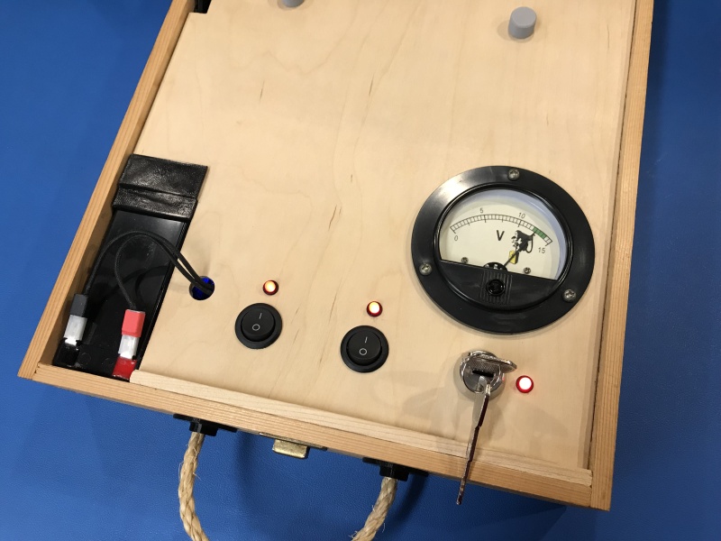
(2) SPST Round Rocker Switches
(1) Key Switch
(1) Micro-USB Cable
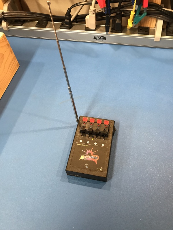
(1) Generic 12-ch Wireless Fireworks TX w/RX units
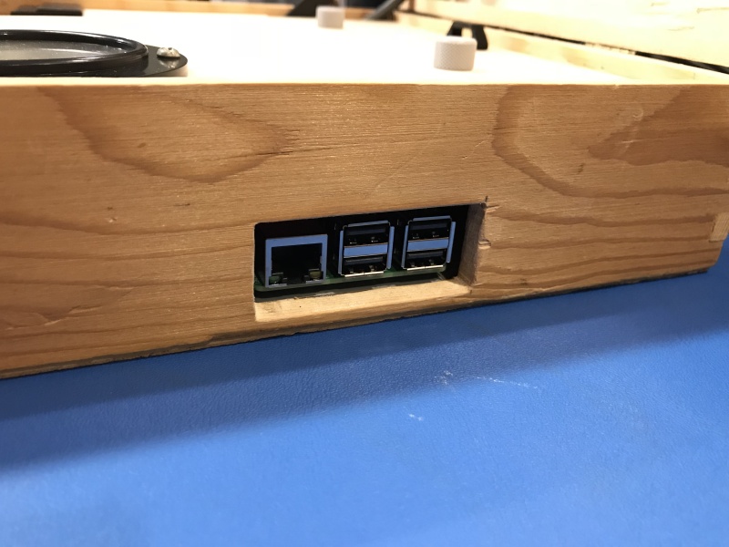
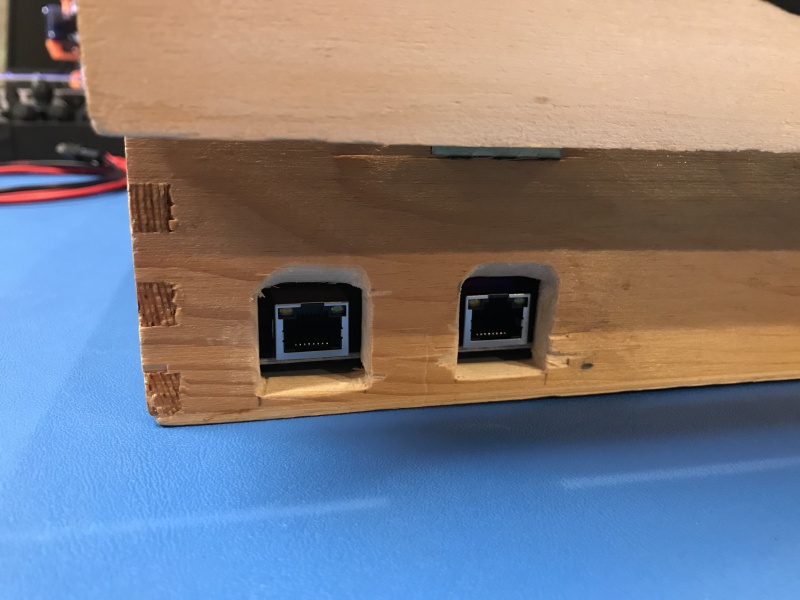
(2) RJ-45 Break-Outs
(1) 80-Piece Breadboard Wire Assortment
(3) 12-position terminal blocks
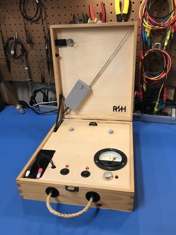
You’ll also need some kind of box to put your project in, and some assorted small pieces of wood. I used an old wine box I found with 3-D printed parts and a hot glue gun to hold most things together.
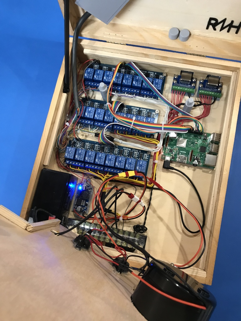
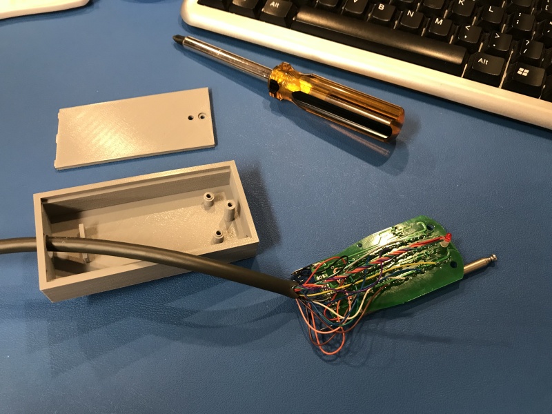
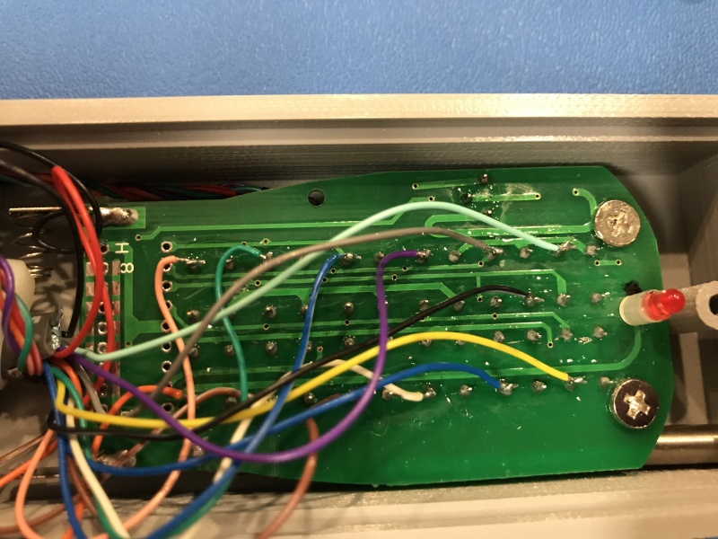
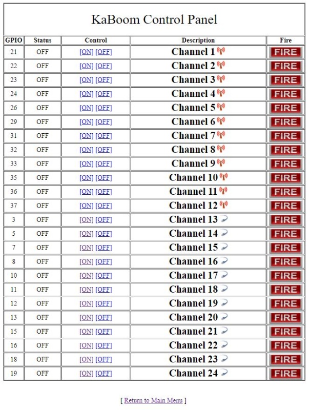
In short, here’s the theory of operation, There’s 26 usable GPIO’s on the Pi3 B+. 24 of them are wired to the 24 relays. 12 of those relays, when thrown, send 12v to the wired RJ45’s on the back (6 channels per jack). This directly triggers the e-matches to ignite the fireworks. The other 12 relays control the 12 wireless firing buttons on the remote that comes with the generic 12-channel fireworks controller. To do this, those relays short a shared ground pin to the ‘on’ pin of each push button switch (see the pics below to see the wiring). I used an old parallel printer cable for the necessary wires, but anything would work. You need 15 wires in total for the fireworks remote. 2 for 12-volt power (supplied only when the arming key is on, 1 for the shared ground, and 12 for the button pins.
To configure the Pi’s Wi-Fi for local access, I followed this great guide at the Raspberry Pi Website:
https://www.raspberrypi.org/documentation/configuration/wireless/access-point.md
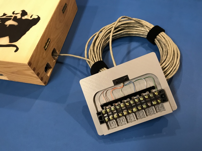
I used the Pi’s wired RJ-45 connection for the test/dev work. All of the control software uses standard python libs for the GPIO pin control to drive the relays, and basic bash scripts running as CGI in Apache. Boards were all mounted using custom 3-D printed stand-offs, and I made a ton of custom 3-D printed parts for things like the handle feed-thru’s, lid prop, control cover stand-offs with threaded caps, battery hold-down, etc. This stuff could all be skipped or accomplished with basic tools, some wood scraps, and more hot glue, but I was going for a certain look and finished quality. Actual interface to the fireworks e-matches is the terminal blocks at the end of 60′ lengths of solid-copper cat5e.
Want another 12 channels? It occurred to me after the initial design that you could add another 12-channel RX/TX set, wired to the same 12 relays you used for the first wireless remote and add 1 more relay to control which remote (TX) gets 12v power when the channel is fired as sort of a ’shift register’.
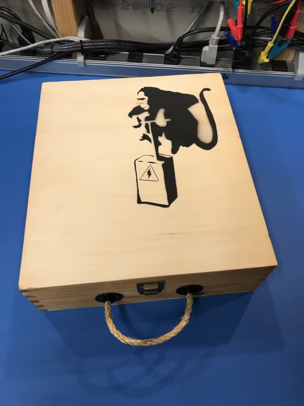
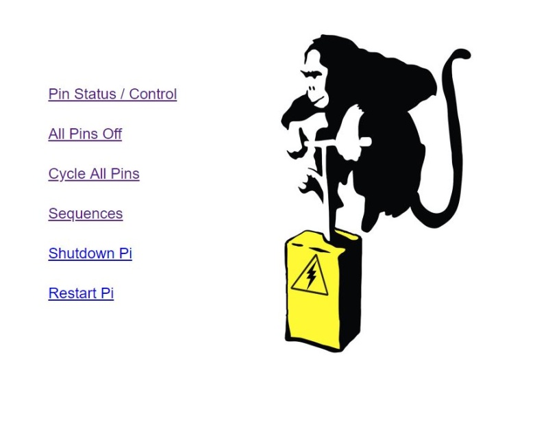
Credit for the stenciled artwork on the box and the graphic in the web/app goes to Banksy. Hopefully he doesn’t mind me using his imagery ![]()
Overall, I am really happy with how this project turned out. It cost less than half what a scriptable 24-channel unit (with the necessary RX/TX modules) would cost, and was a bunch of fun to design and build. Even had my 9-yr old interested through the process. She was checking in each time I worked on it to see what was new/working.
I’ll post up a video of the full show when it happens this 4th of July, but here’s 3 test shots, timed a half-second apart from left to right:
https://www.youtube.com/watch?v=xHI18-IAhEE (taken from DJI Mavic drone)
More pics below, and full size images available on my gallery page:
Kevin
July 3rd, 2018
We both used the same relay module for each of our fireworks launcher systems.
Nice touch with mix of 12 programmed launch positions and 12 manually triggered wireless positions, if i interpreted your article correctly.
Rich
July 3rd, 2018
Thanks, I like the way you angled the relay boards to route the wiring underneath. Very clean.
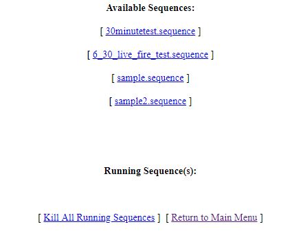
12-wired and 12-wireless, but all can be triggered manually through the web interface -OR- fired as part of a programmatic script (sequence).